


Selection of NPN and PNP photoelectric sensors
#news ·2025-10-19 08:55:52


The distinction between NPN and PNP photoelectric sensor types is primarily based on the structure of their output circuits and signal processing methods, which directly affects their compatibility with control systems (such as PLCs and relay modules). The following analysis will be conducted from the perspectives of technical principles, output characteristics, application scenarios, and key selection criteria:
1. Technical Principles and Circuit Structure Differences
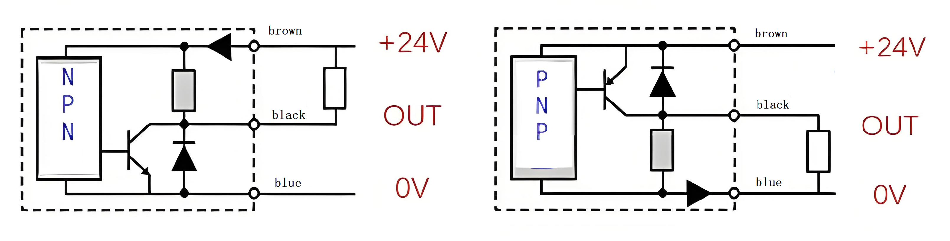
The NPN-type photoelectric sensor employs a common emitter circuit configuration, where its output terminal (collector) is connected to the positive terminal of the power supply via a load resistor. When the sensor detects an object, the internal transistor turns on, creating a low-level signal between the output terminal and ground (0V). At this point, the load current flows from the positive terminal of the power supply through the load resistor, the sensor's output terminal, and then to ground, forming a closed circuit.
The PNP-type photoelectric sensor employs a common collector circuit configuration, where the output terminal (emitter) is directly connected to the positive power supply. When the sensor is activated, the internal transistor turns on, forming a high-level signal between the output terminal and the positive power supply. At this point, the load current flows from the sensor output terminal through the load resistor to ground, but the signal logic is active-high.
The core difference lies in signal polarity: an NPN output low level (0V) serves as the active signal, while a PNP output high level (supply voltage) functions as the active signal. This distinction stems from the transistor types (NPN has a negative-positive-negative structure, whereas PNP has a positive-negative-positive structure) and the differences in circuit connection methods.
2. Output Characteristics and Signal Logic
The output signal of an NPN-type sensor is "low-level active," meaning it outputs 0V when a target is detected and enters a high-impedance or power supply voltage state when no target is detected. Its advantages include strong anti-interference capability (low-level signals are less affected by noise), making it suitable for applications requiring long-distance transmission or environments with electromagnetic interference. However, it is important to note that the load must be connected to the positive terminal of the power supply, and the output current flows into the sensor.
The output signal of a PNP-type sensor is "high level active," meaning it outputs the power supply voltage when a target is detected and 0V when no target is detected. Its advantage lies in the ability to directly drive loads requiring high-level triggering (such as certain PLC input modules), with the output current direction flowing out of the sensor. However, high-level signals may be affected by voltage drop during long-distance transmission, necessitating proper selection of wire gauge.
3. Application Scenarios and Selection Criteria
Control System Compatibility: If the input of the PLC or relay module is "source-type input" (i.e., the input terminal needs to be connected to the positive terminal of the power supply to receive current), a PNP-type sensor should be selected; if it is "sink-type input" (the input terminal needs to be connected to ground to release current), an NPN-type sensor should be selected. For example, the input modules of the Siemens S7-200 series PLC are typically compatible with NPN-type sensors, while the Mitsubishi FX series may require PNP-type sensors.
Load Type: If the load is an equipment requiring high-current drive, such as a relay or solenoid valve, the sensor type must be selected based on the load power polarity. For example, if the load power is 24V DC and the positive terminal is connected to the sensor output, a PNP type is required; if the negative terminal is connected to the output, an NPN type is required.
Environmental Adaptability: In environments with strong electromagnetic interference, NPN-type low-level signals are more stable; whereas in scenarios requiring rapid response or high-level triggering (such as high-speed counting), PNP-type may be more suitable.
4. Selection and Usage Precautions
Voltage matching: Ensure the sensor's power supply voltage is consistent with the control system (e.g., 24V DC) to prevent damage caused by voltage mismatch.
Load current: Verify whether the sensor's output current meets the load requirements (e.g., relay coil current). The output current capability of NPN and PNP types is generally the same, but attention must be paid to the current direction.
Wiring Verification: Use a multimeter to measure the voltage between the sensor output terminal and ground/positive power supply, and confirm whether the signal polarity matches the expected behavior during operation.
Redundant Design: In critical applications, NPN and PNP-type sensors can be installed simultaneously to enhance system reliability through a logical OR configuration.